Article purpose
The objective of this article is to explore Image Edge Detection implemented by means of Image Dilation and Image Erosion morphological filters. In addition we explore the concept of Image Sharpening implementing morphological edge detection.
Sample source code
This article is accompanied by a sample source code Visual Studio project which is available for download here.
Using the sample application
This article is accompanied by a Sample Application intended to implement all of the concepts illustrated throughout this article. Using the sample application users can easily test and replicate concepts.
Clicking the Load Image button allows users to select source/input images from the local file system. Filter option categories are: Colour(s), morphology type, edge options and filter size.
This article and sample source code can process colour images as source images. The user can specify which colour components to include in resulting images. The three checkboxes labelled Red, Green and Blue indicate whether the related colour component features in result images.
The four radiobuttons labelled Dilate, Erode, Open and Closed enable the user to select the type of morphological filter to apply.
Edge detection options include: None, Edge Detection and Image Sharpening. Selecting None results in only the selected morphological filter being applied.
Filter sizes range from 3×3 up to 17×17. The filter size specified determines the intensity of the morphological filter applied.
If desired users are able to save filter result images to the local file system by clicking the Save Image button. The image below is a screenshot of the Morphological Edge Detection sample application in action:
Morphology – Image Erosion and Dilation
Image Erosion and Dilation are implementations of morphological filters, a subset of Mathematical Morphology. In simpler terms Image Dilation can be defined by this quote:
Dilation is one of the two basic operators in the area of mathematical morphology, the other being erosion. It is typically applied to binary images, but there are versions that work on grayscale images. The basic effect of the operator on a binary image is to gradually enlarge the boundaries of regions of foreground pixels (i.e. white pixels, typically). Thus areas of foreground pixels grow in size while holes within those regions become smaller.
Image Erosion being a related concept is defined by this quote:
Erosion is one of the two basic operators in the area of mathematical morphology, the other being dilation. It is typically applied to binary images, but there are versions that work on grayscale images. The basic effect of the operator on a binary image is to erode away the boundaries of regions of foreground pixels (i.e. white pixels, typically). Thus areas of foreground pixels shrink in size, and holes within those areas become larger.
From the definitions listed above we gather that Image Dilation increases the size of edges contained in an image. In contrast Image Erosion decreases or shrinks the size of an Image’s edges.
Image Edge Detection
We gain a good definition of edge detection from Wikipedia’s article on edge detection:
Edge detection is the name for a set of mathematical methods which aim at identifying points in a digital image at which the image brightness changes sharply or, more formally, has discontinuities. The points at which image brightness changes sharply are typically organized into a set of curved line segments termed edges. The same problem of finding discontinuities in 1D signals is known as step detection and the problem of finding signal discontinuities over time is known as change detection. Edge detection is a fundamental tool in image processing, machine vision and computer vision, particularly in the areas of feature detection and feature extraction.
In this article we implement edge detection based on the type of morphology being performed. In the case of Image Erosion the eroded image is subtracted from the original image resulting in an image with pronounced edges. When implementing Image Dilation, edge detection is achieved by subtracting the original image from the dilated image.
Image Sharpening
Image Sharpening is often referred to by the term Edge Enhancement, from Wikipedia we gain the following definition:
Edge enhancement is an image processing filter that enhances the edge contrast of an image or video in an attempt to improve its acutance (apparent sharpness).
The filter works by identifying sharp edge boundaries in the image, such as the edge between a subject and a background of a contrasting color, and increasing the image contrast in the area immediately around the edge. This has the effect of creating subtle bright and dark highlights on either side of any edges in the image, called overshoot and undershoot, leading the edge to look more defined when viewed from a typical viewing distance.
In this article we implement Image Sharpening by first creating an edge detection image which we then add to the original image, resulting in an image with enhanced edges.
Implementing Morphological Filters
The sample source code provides the definition of the DilateAndErodeFilter extension method targeting the Bitmap class. The DilateAndErodeFilter extension method as a single method implementation is capable of applying a specified morphological filter, edge detection and Image Sharpening. The following code snippet details the implementation of the the DilateAndErodeFilter extension method:
public static Bitmap DilateAndErodeFilter(this Bitmap sourceBitmap,
                                        int matrixSize,
                                        MorphologyType morphType,
                                        bool applyBlue = true,
                                        bool applyGreen = true,
                                        bool applyRed = true,
                                        MorphologyEdgeType edgeType =
                                        MorphologyEdgeType.None)
{
    BitmapData sourceData =
               sourceBitmap.LockBits(new Rectangle (0, 0,
               sourceBitmap.Width, sourceBitmap.Height),
               ImageLockMode.ReadOnly,
               PixelFormat.Format32bppArgb);


    byte[] pixelBuffer = new byte[sourceData.Stride *
                                  sourceData.Height];


    byte[] resultBuffer = new byte[sourceData.Stride *
                                   sourceData.Height];


    Marshal.Copy(sourceData.Scan0, pixelBuffer, 0,
                               pixelBuffer.Length);


    sourceBitmap.UnlockBits(sourceData);


    int filterOffset = (matrixSize - 1) / 2;
    int calcOffset = 0;


    int byteOffset = 0;


    int blue = 0;
    int green = 0;
    int red = 0;


    byte morphResetValue = 0;


    if (morphType == MorphologyType.Erosion)
    {
        morphResetValue = 255;
    }


    for (int offsetY = filterOffset; offsetY <
        sourceBitmap.Height - filterOffset; offsetY++)
    {
        for (int offsetX = filterOffset; offsetX <
            sourceBitmap.Width - filterOffset; offsetX++)
        {
            byteOffset = offsetY *
                         sourceData.Stride +
                         offsetX * 4;


            blue = morphResetValue;
            green = morphResetValue;
            red = morphResetValue;


            if (morphType == MorphologyType.Dilation)
            {
                for (int filterY = -filterOffset;
                    filterY <= filterOffset; filterY++)
                {
                    for (int filterX = -filterOffset;
                        filterX <= filterOffset; filterX++)
                    {
                        calcOffset = byteOffset +
                                     (filterX * 4) +
                        (filterY * sourceData.Stride);


                        if (pixelBuffer[calcOffset] > blue)
                        {
                            blue = pixelBuffer[calcOffset];
                        }


                        if (pixelBuffer[calcOffset + 1] > green)
                        {
                            green = pixelBuffer[calcOffset + 1];
                        }


                        if (pixelBuffer[calcOffset + 2] > red)
                        {
                            red = pixelBuffer[calcOffset + 2];
                        }
                    }
                }
            }
            else if (morphType == MorphologyType.Erosion)
            {
                for (int filterY = -filterOffset;
                    filterY <= filterOffset; filterY++)
                {
                    for (int filterX = -filterOffset;
                        filterX <= filterOffset; filterX++)
                    {
                        calcOffset = byteOffset +
                                     (filterX * 4) +
                        (filterY * sourceData.Stride);


                        if (pixelBuffer[calcOffset] < blue)
                        {
                            blue = pixelBuffer[calcOffset];
                        }


                        if (pixelBuffer[calcOffset + 1] < green)
                        {
                            green = pixelBuffer[calcOffset + 1];
                        }


                        if (pixelBuffer[calcOffset + 2] < red)
                        {
                            red = pixelBuffer[calcOffset + 2];
                        }
                    }
                }
            }


            if (applyBlue == false )
            {
                blue = pixelBuffer[byteOffset];
            }


            if (applyGreen == false )
            {
                green = pixelBuffer[byteOffset + 1];
            }


            if (applyRed == false )
            {
                red = pixelBuffer[byteOffset + 2];
            }


            if (edgeType == MorphologyEdgeType.EdgeDetection ||
                edgeType == MorphologyEdgeType.SharpenEdgeDetection)
            {
                if (morphType == MorphologyType.Dilation)
                {
                    blue = blue - pixelBuffer[byteOffset];
                    green = green - pixelBuffer[byteOffset + 1];
                    red = red - pixelBuffer[byteOffset + 2];
                }
                else if (morphType == MorphologyType.Erosion)
                {
                    blue = pixelBuffer[byteOffset] - blue;
                    green = pixelBuffer[byteOffset + 1] - green;
                    red = pixelBuffer[byteOffset + 2] - red;
                }


                if (edgeType == MorphologyEdgeType.SharpenEdgeDetection)
                {
                    blue += pixelBuffer[byteOffset];
                    green += pixelBuffer[byteOffset + 1];
                    red += pixelBuffer[byteOffset + 2];
                }
            }


            blue = (blue > 255 ? 255 : (blue < 0 ? 0 : blue));
            green = (green > 255 ? 255 : (green < 0 ? 0 : green));
            red = (red > 255 ? 255 : (red < 0 ? 0 : red));


            resultBuffer[byteOffset] = (byte)blue;
            resultBuffer[byteOffset + 1] = (byte)green;
            resultBuffer[byteOffset + 2] = (byte)red;
            resultBuffer[byteOffset + 3] = 255;
        }
    }


    Bitmap resultBitmap = new Bitmap(sourceBitmap.Width,
                                     sourceBitmap.Height);


    BitmapData resultData =
               resultBitmap.LockBits(new Rectangle(0, 0,
               resultBitmap.Width, resultBitmap.Height),
               ImageLockMode.WriteOnly,
               PixelFormat.Format32bppArgb);


    Marshal.Copy(resultBuffer, 0, resultData.Scan0,
                               resultBuffer.Length);


    resultBitmap.UnlockBits(resultData);


    return resultBitmap;
}
Sample Images
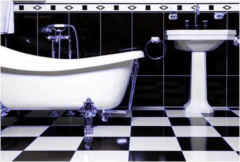
The source/input image used in this article is licensed under the Creative Commons Attribution-Share Alike 3.0 Unported license and can be downloaded from Wikipedia: http://en.wikipedia.org/wiki/File:Bathroom_with_bathtube.jpg
Original Image
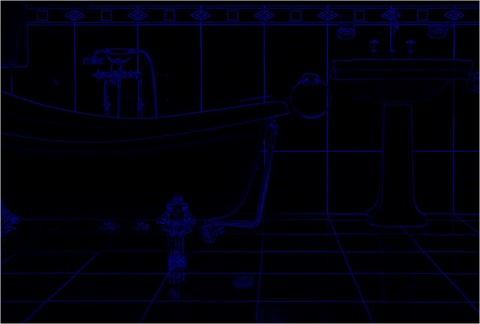
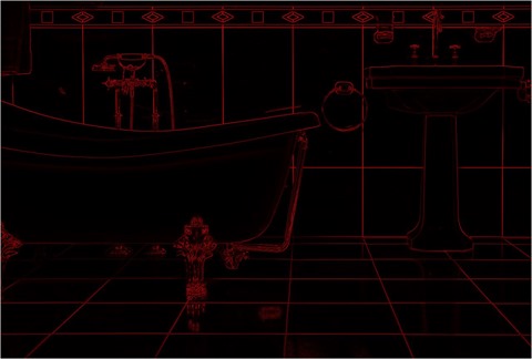
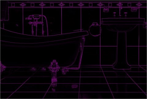
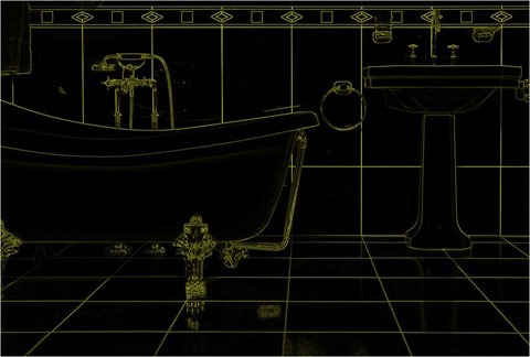
Erosion 3×3, Edge Detect, Red, Green and Blue
Erosion 3×3, Edge Detect, Blue
Erosion 3×3, Edge Detect, Green and Blue
Erosion 3×3, Edge Detect, Red
Erosion 3×3, Edge Detect, Red and Blue
Erosion 3×3, Edge Detect, Red and Green
Erosion 7×7, Sharpen, Red, Green and Blue
Erosion 7×7, Sharpen, Blue
Erosion 7×7, Sharpen, Green
Erosion 7×7, Sharpen, Green and Blue
Erosion 7×7, Sharpen, Red
Erosion 7×7, Sharpen, Red and Blue
Erosion 7×7, Sharpen, Red and Green
Related Articles and Feedback
Feedback and questions are always encouraged. If you know of an alternative implementation or have ideas on a more efficient implementation please share in the comments section.
I’ve published a number of articles related to imaging and images of which you can find URL links here:
- C# How to: Image filtering by directly manipulating Pixel ARGB values
- C# How to: Image filtering implemented using a ColorMatrix
- C# How to: Blending Bitmap images using colour filters
- C# How to: Bitmap Colour Substitution implementing thresholds
- C# How to: Generating Icons from Images
- C# How to: Swapping Bitmap ARGB Colour Channels
- C# How to: Bitmap Pixel manipulation using LINQ Queries
- C# How to: Linq to Bitmaps – Partial Colour Inversion
- C# How to: Bitmap Colour Balance
- C# How to: Bi-tonal Bitmaps
- C# How to: Bitmap Colour Tint
- C# How to: Bitmap Colour Shading
- C# How to: Image Solarise
- C# How to: Image Contrast
- C# How to: Bitwise Bitmap Blending
- C# How to: Image Arithmetic
- C# How to: Image Convolution
- C# How to: Image Edge Detection
- C# How to: Difference Of Gaussians
- C# How to: Image Median Filter
Filed under: Augmented Reality, C#, Code Samples, Edge Detection, Extension Methods, Graphic Filters, Graphics, How to, Image Convolution, Image Filters, Learn Everyday, Microsoft, Morphology Filters, New Version, Opensource, Tip Tagged: Augmented Reality, Bitmap ARGB, Bitmap Filters, Bitmap.LockBits, BitmapData, C#, Code Sample, Computer vision, Convolution filters, Convolution Kernel, Convolution matrix, Feature extraction, Graphic Filters, Image, Image Dilation, Image Edge Detection, Image Erosion, Image Morphology, Image processing, Image Transform, Machine vision, Matrix, Pixel Filters, Pixel Manipulation


